DRO – off we go!

Well, I thought it about time I fitted the DRO kit to my F3. I bought the kit from Machine-DRO (part of the Allendale Group) – only because I have bought from them before and found them to be very helpful. The 3 axis kit is suitable for a Bridgeport and seems to costs no more for longer scales, the scales being of the slim magnetic type.

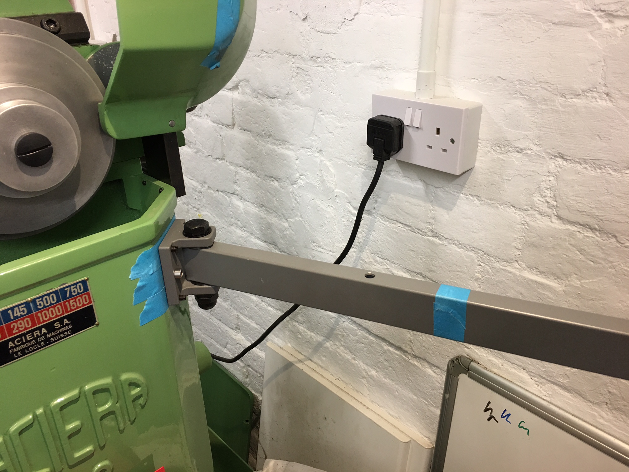
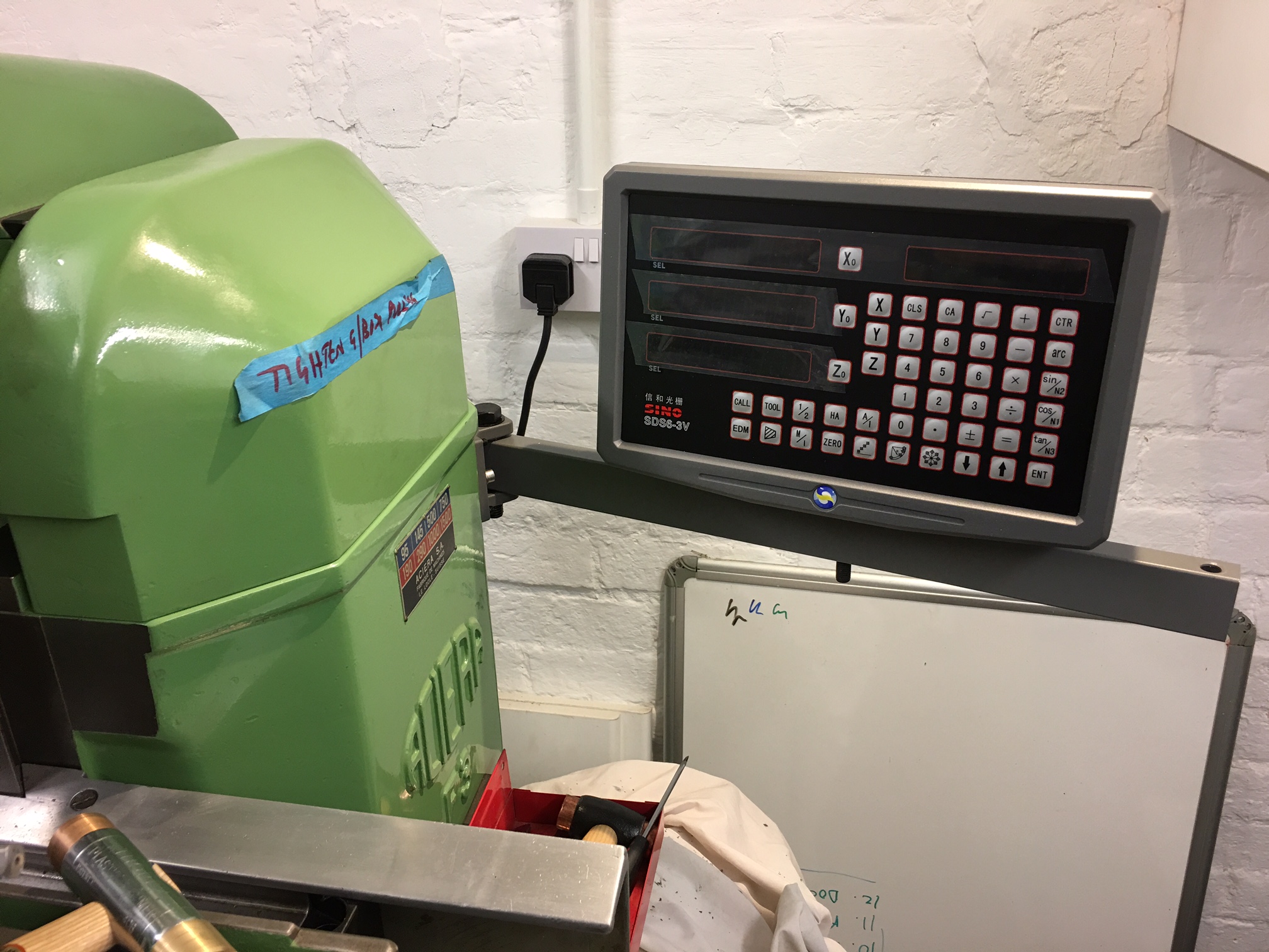
First task is to mount the readout unit. As you can see the arm is longer than required but allows mew to position the unit where I am happy with it. I can then saw off the spare length.

I’m fairly happy with the position but I won’t cut the bar until the last moment.

Now onto the scales…..


Slow progress!

I have been busy building a new shop for the F3 mill and it has taken a lot longer than anticipated – together with the fact that the house is now on the market, its a busy time.

Anyway, I hope to purchase the DRO in the next few weeks and have that installed before Christmas…….


Oil Sight Glass repair

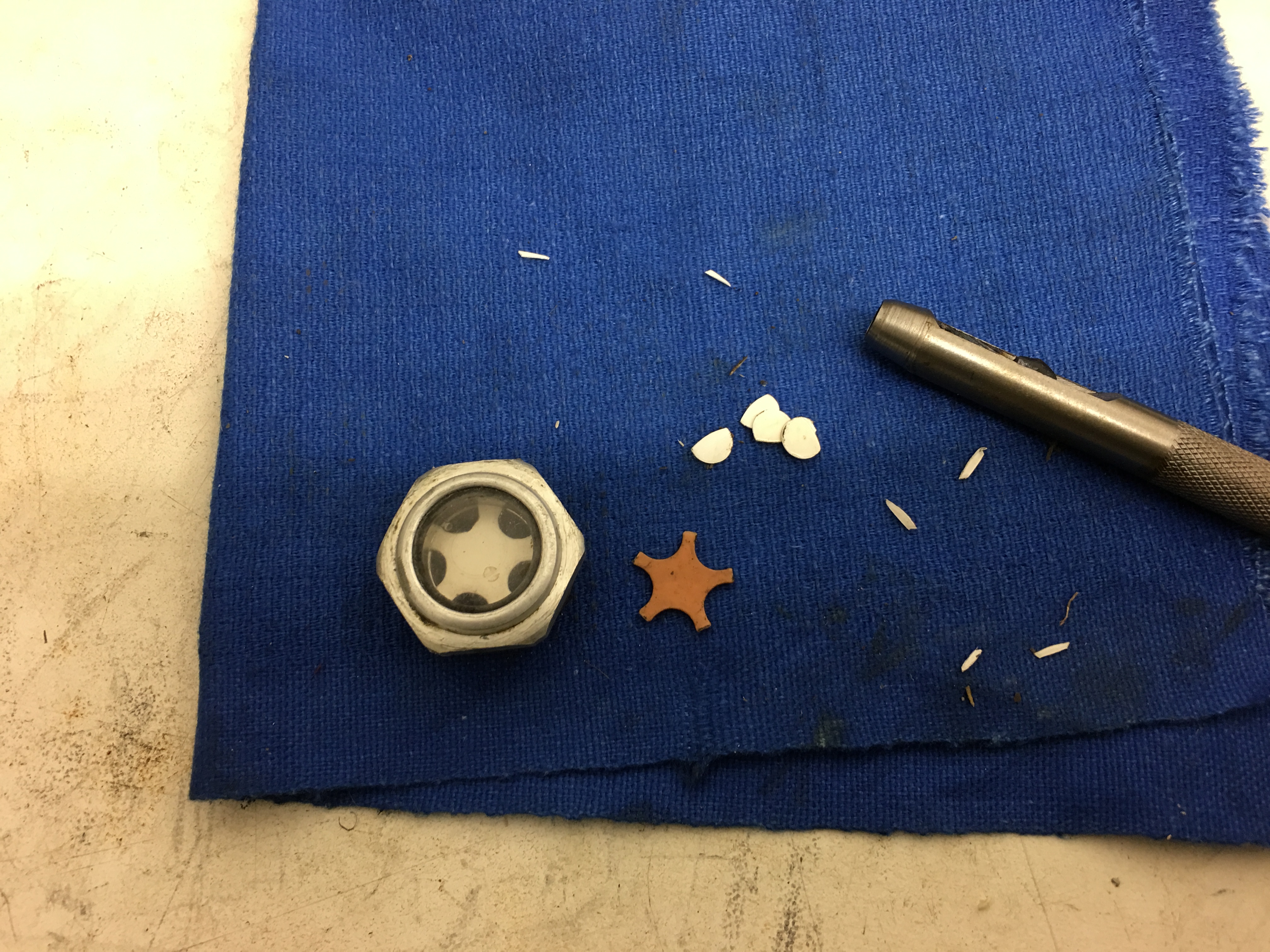
The picture shows the original sight glass for the horizontal head wiht the replaced plastic insert. The riginal insert was almost the same colour as the oil and so made for poor visibility. One plastic card and a selection of wad punches later and I had made a new insert. The sight glass now looks as good as new!!

oil_glass_repair

Now I’m ready for the oil and to fire up the F3!!

Gearbox pulley

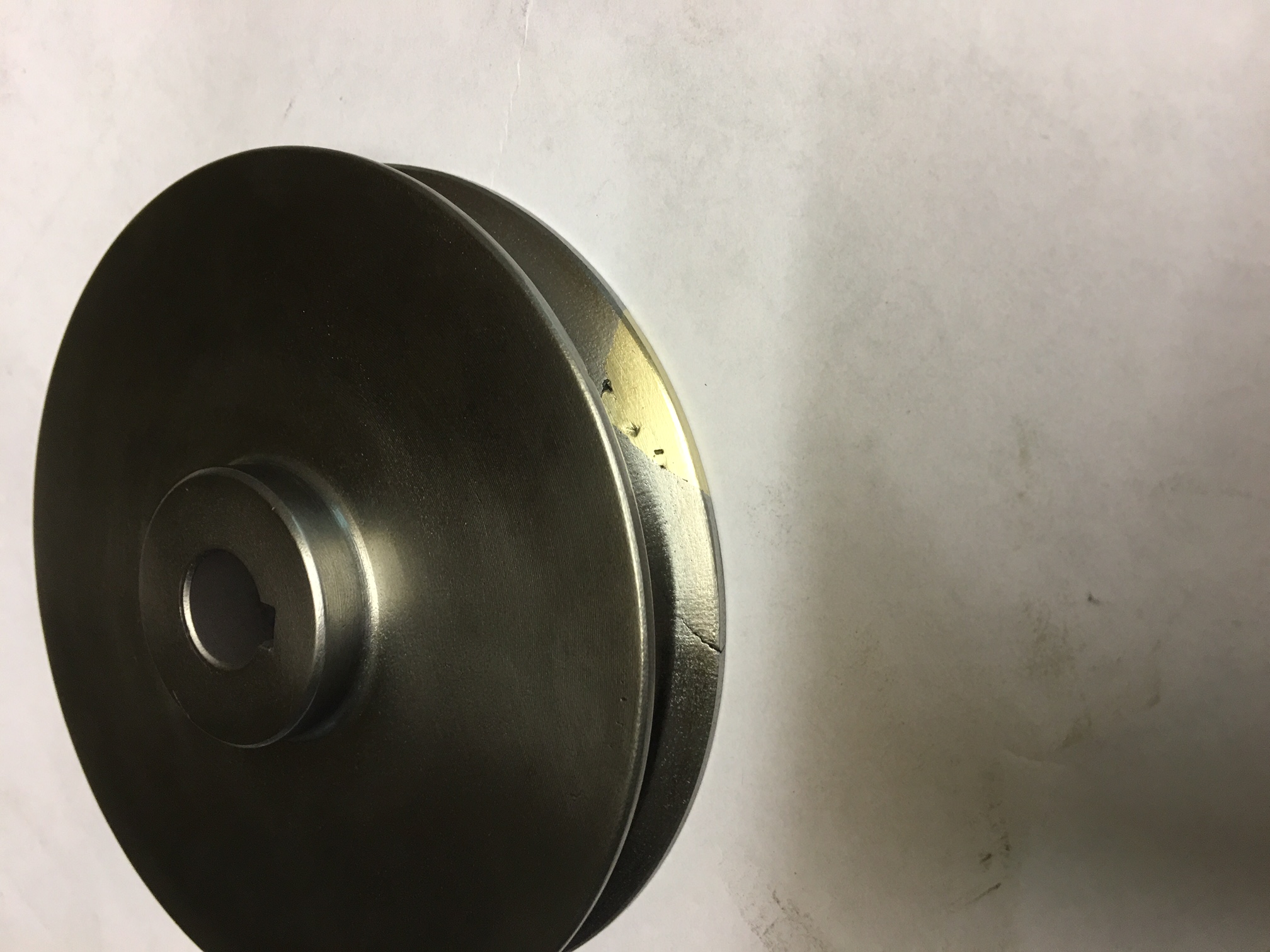
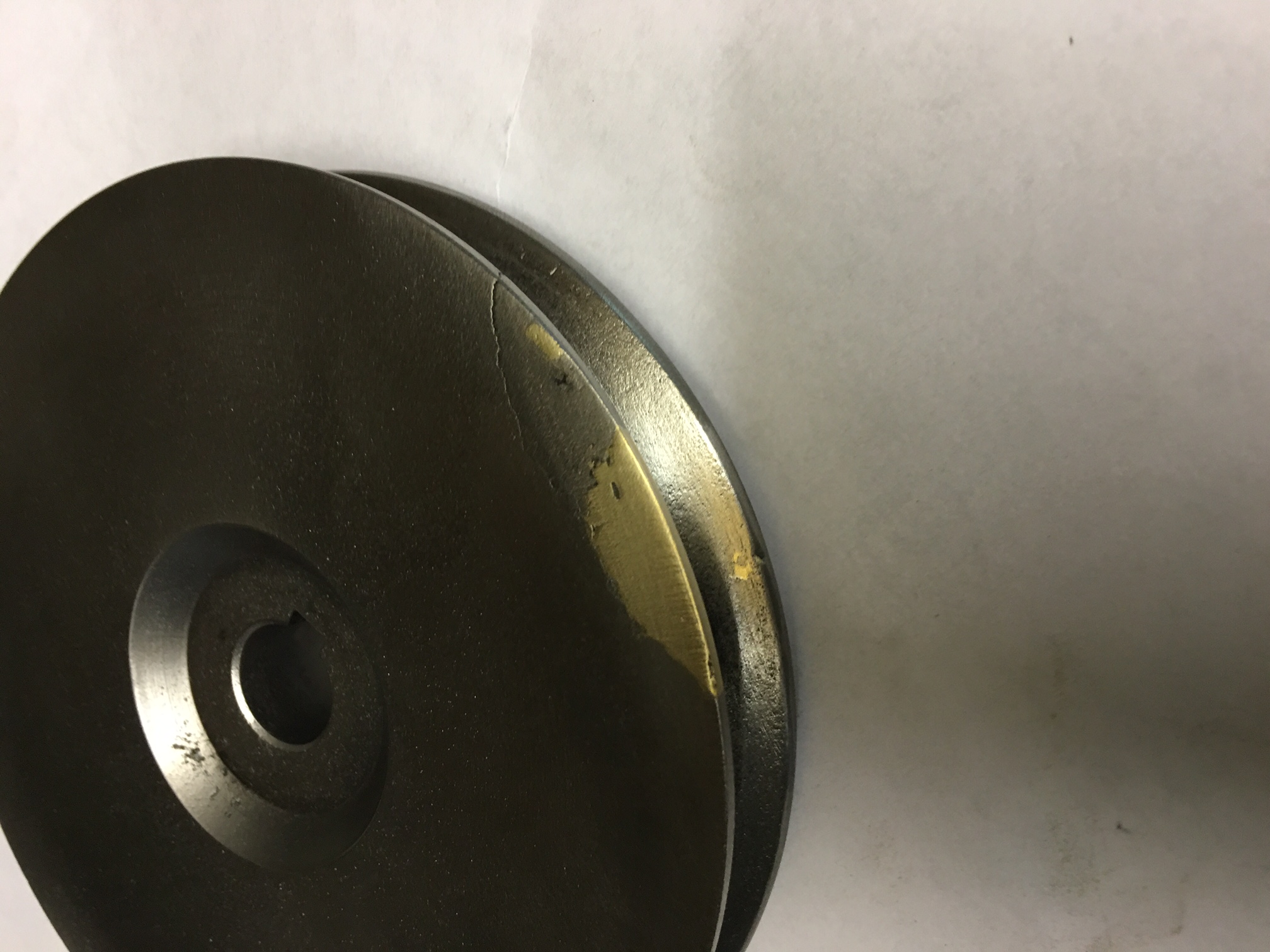
I think I mentioned that the pullet came off the spindle a little quicker than I had anticipated and when it hit the motor, I noticed the pulley was cracked and chipped. Inspection revealed it was cracked before as the metal had rust in the crack. Anyway, I decided to braze the pulley and then skim it back to shape on the lathe. Below are two phots looking at either side of the pulley. You will notice that there is still a crack in the pulley but hopefully the braze will keep it all together.

IMG_2763 IMG_2764

Worse case is that if it failes again, I will either make a new pulley or braze up the other portion.

Inverter

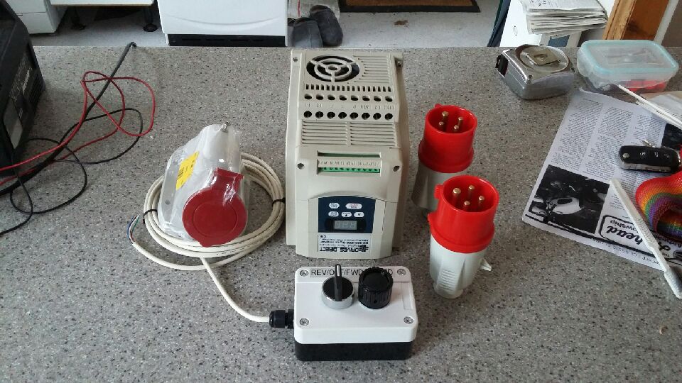
After a lot of thought, I decided the best way forward was to fit an inverter. I was lucky enought to get a new inverter at a sensible price – 240v single phase in , 415v 3 phase out. It is a 2HP model, so should match up well to the motor. (which is only a single voltage motor but twin speed).This should make life a little easier for me as far as wiring up is concerned. I may try and work out how to wire in an LED speed indicator…..

inverter

It is currently with a friend who picked it up for me.

I’m not sure whether to mount a control box on the back of the machine or have the VFD mounted away from the machine. I’m a way off from having to worry about this yet.

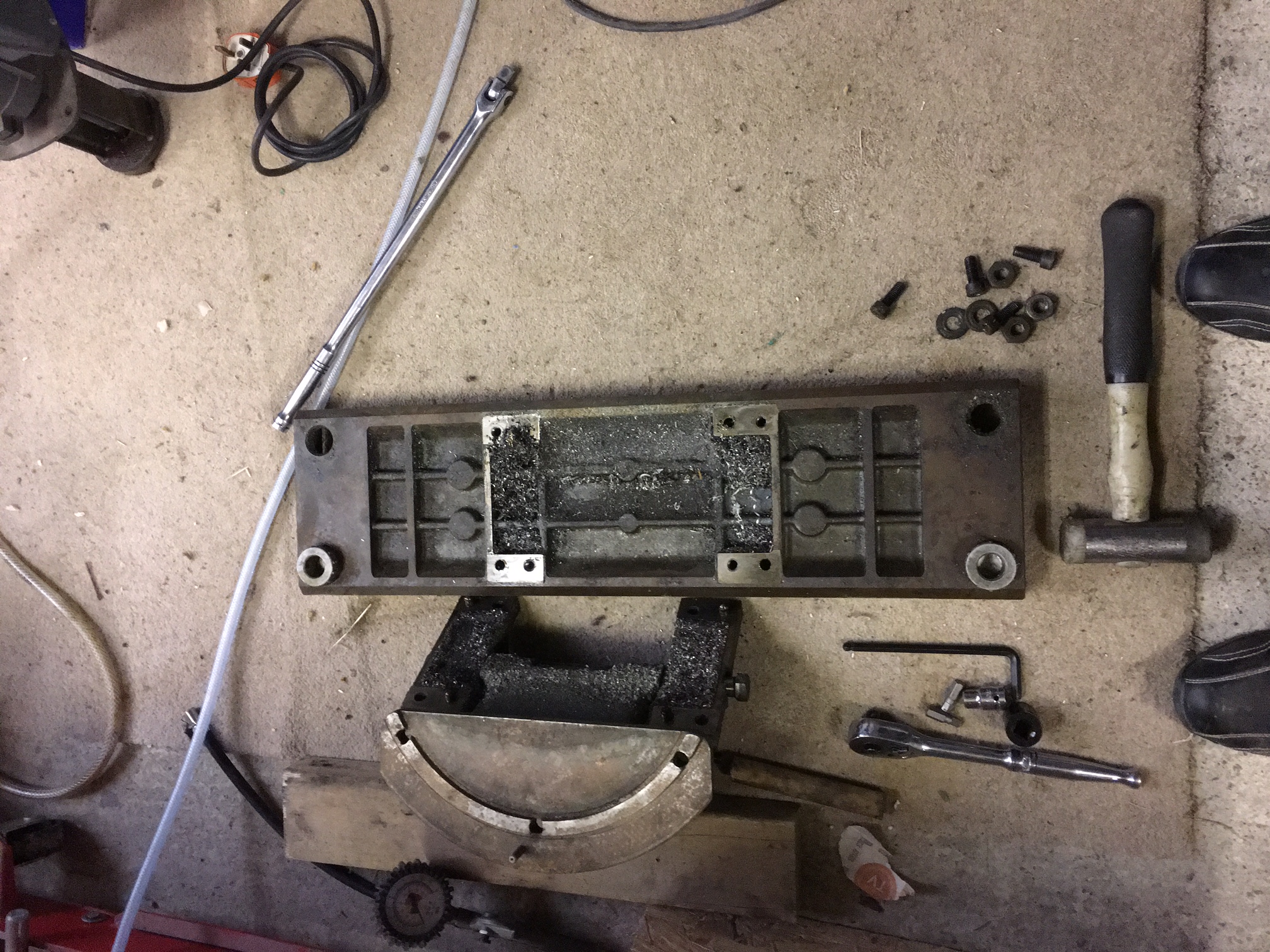
A clean table

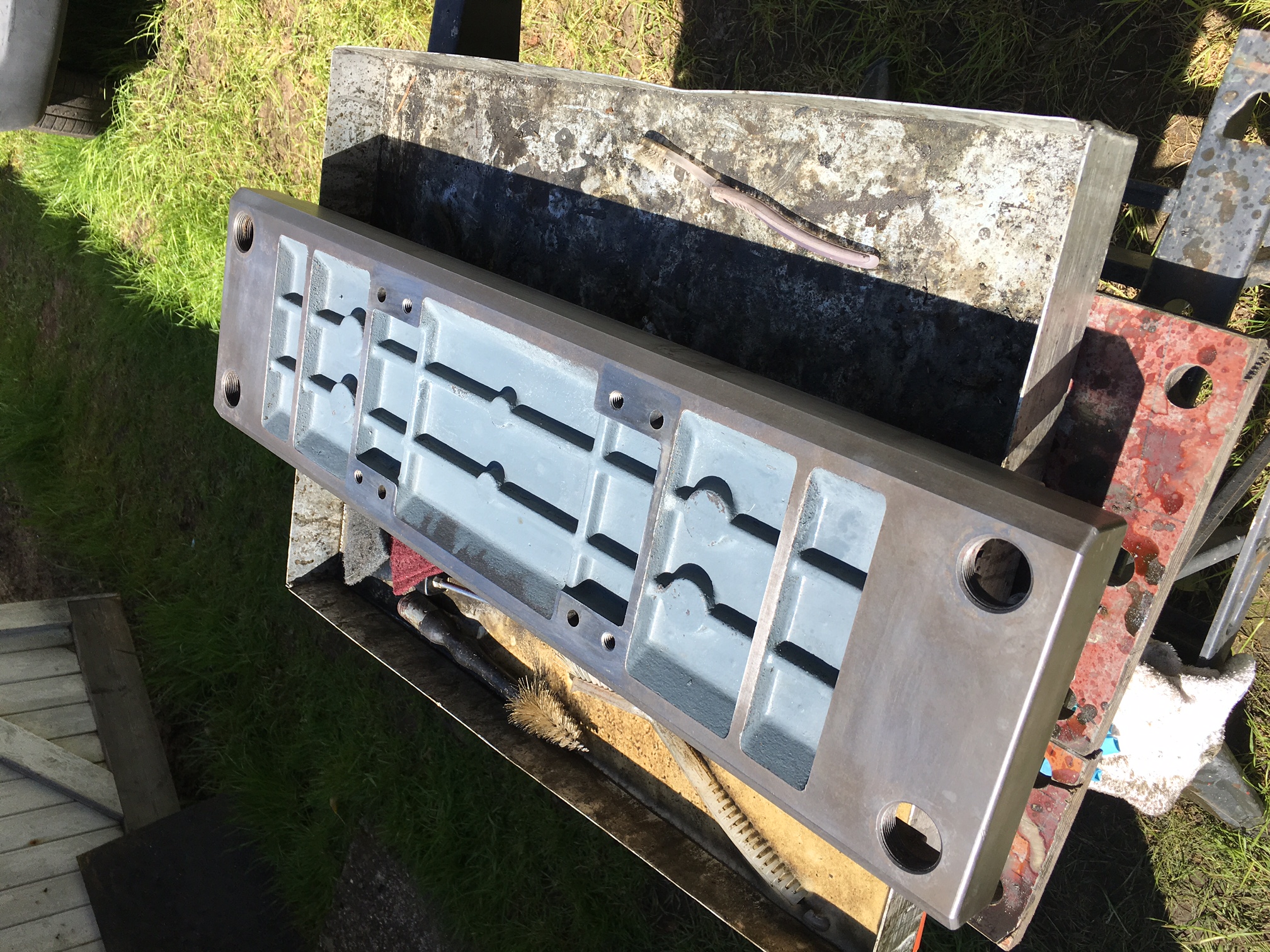
I vary the cleaning of the parts from using an aqueous alkaline degreaser to a solvent based one. I have yet to decide which is the better, however, when the sun is shining then I prefer to do the job outside and use the water based one! I use a fine scotchbrite pad when cleaning and this cleans off the dirt and any fine rust. Below is the table before cleaning.
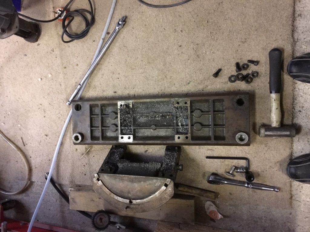
IMG_2721

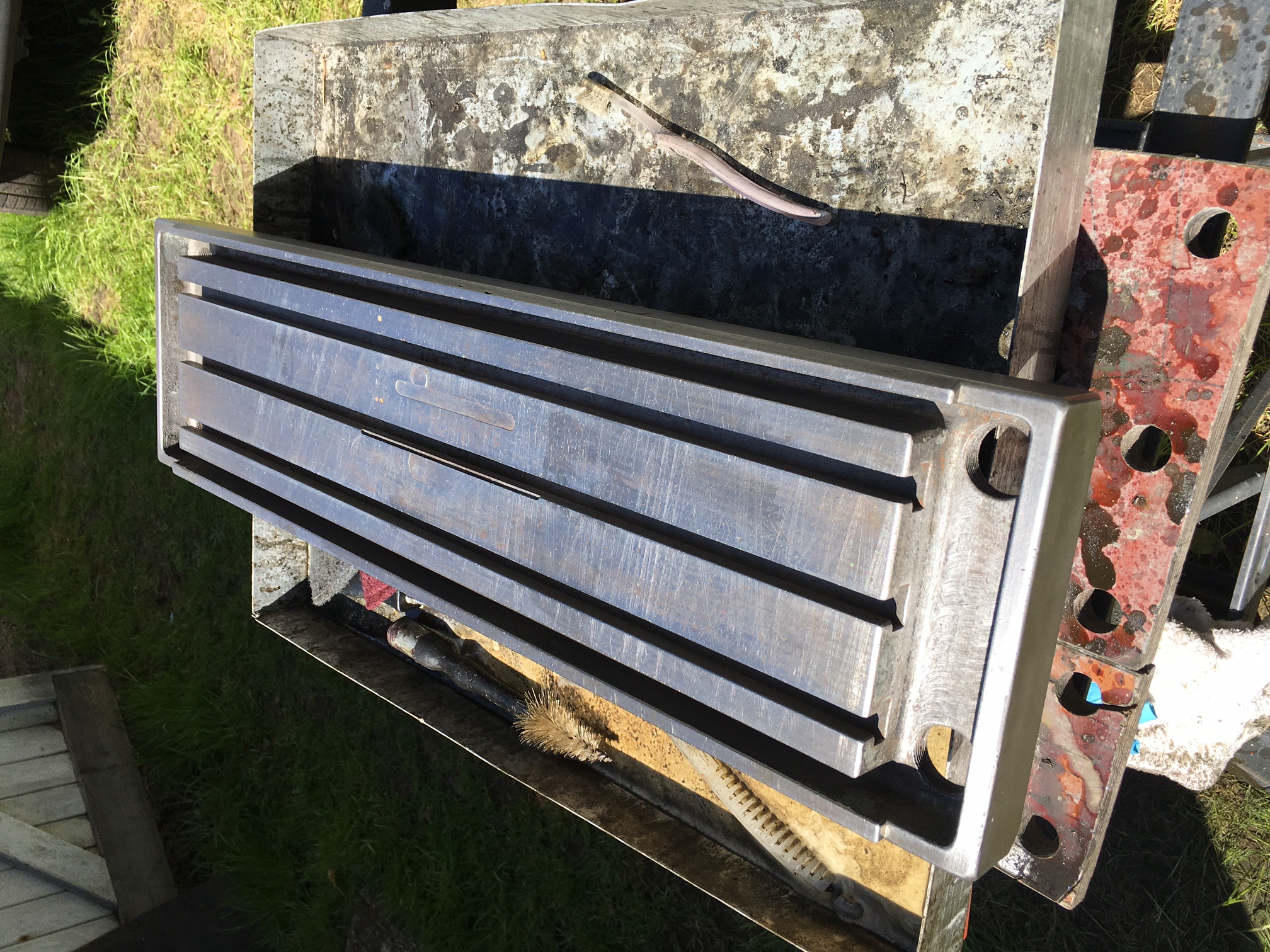
As you can see, it has come up reasonablty well. This is stage one and I will clean the top surface a bit more using the same techniques as I did on the apron slide.
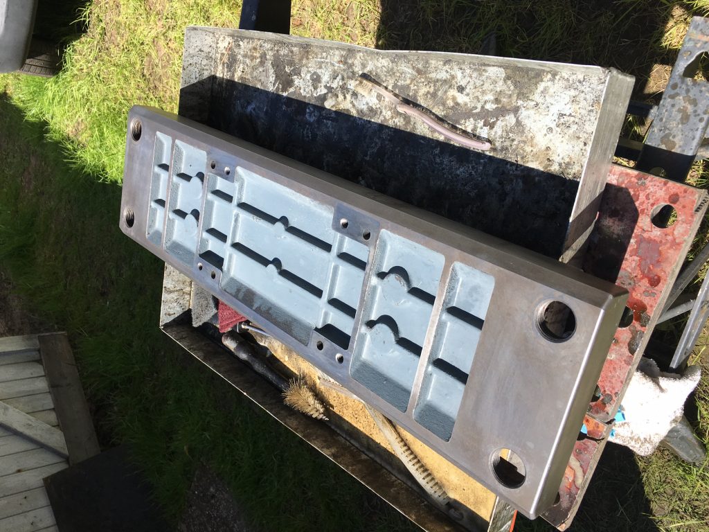
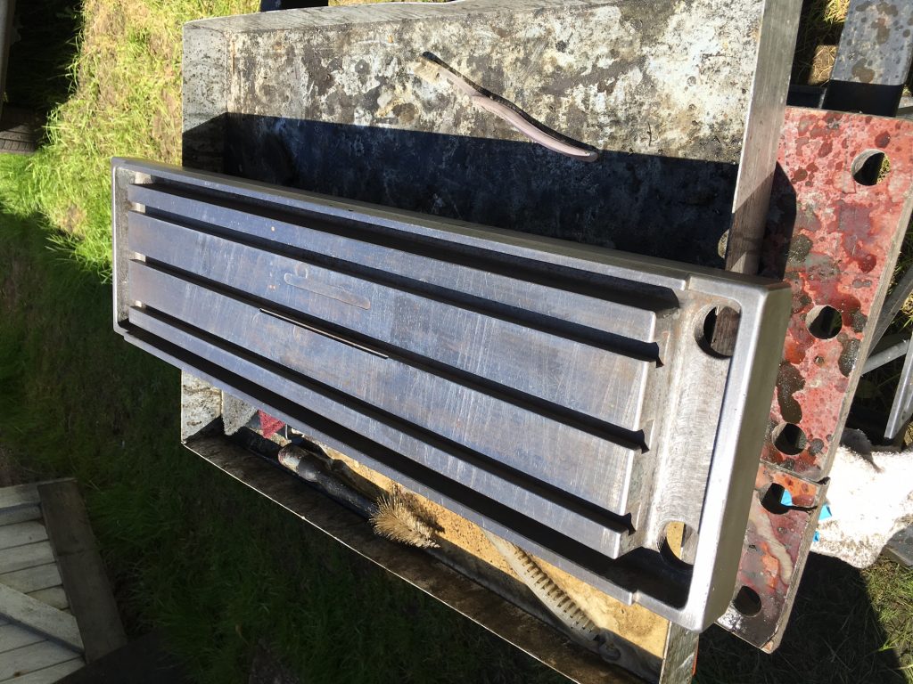
IMG_2743 IMG_2745

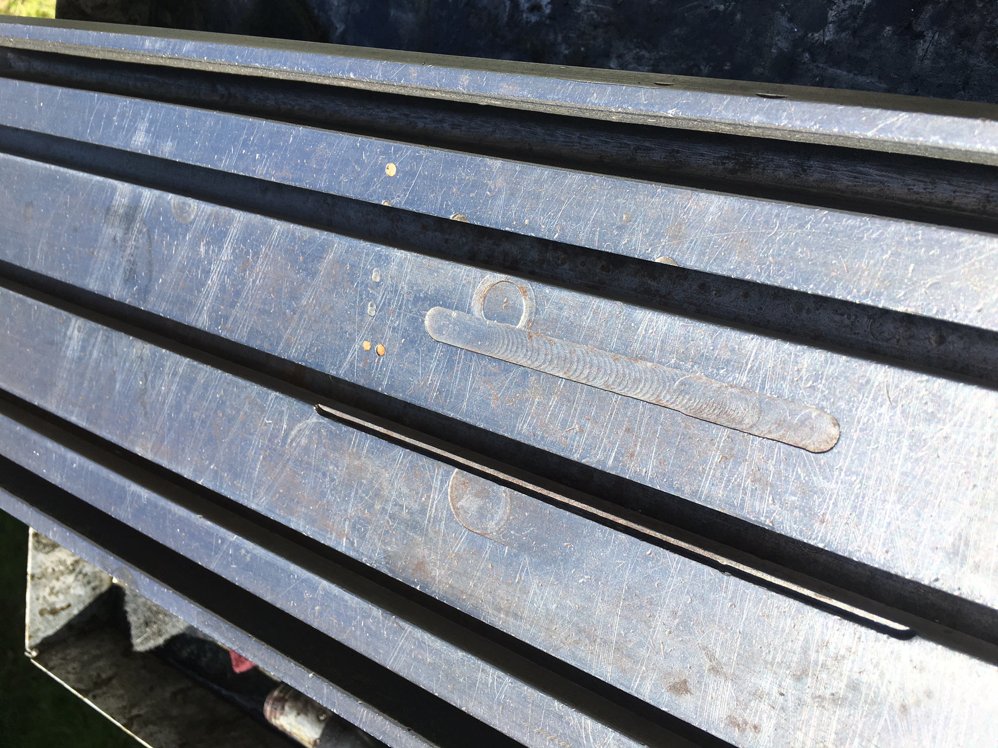
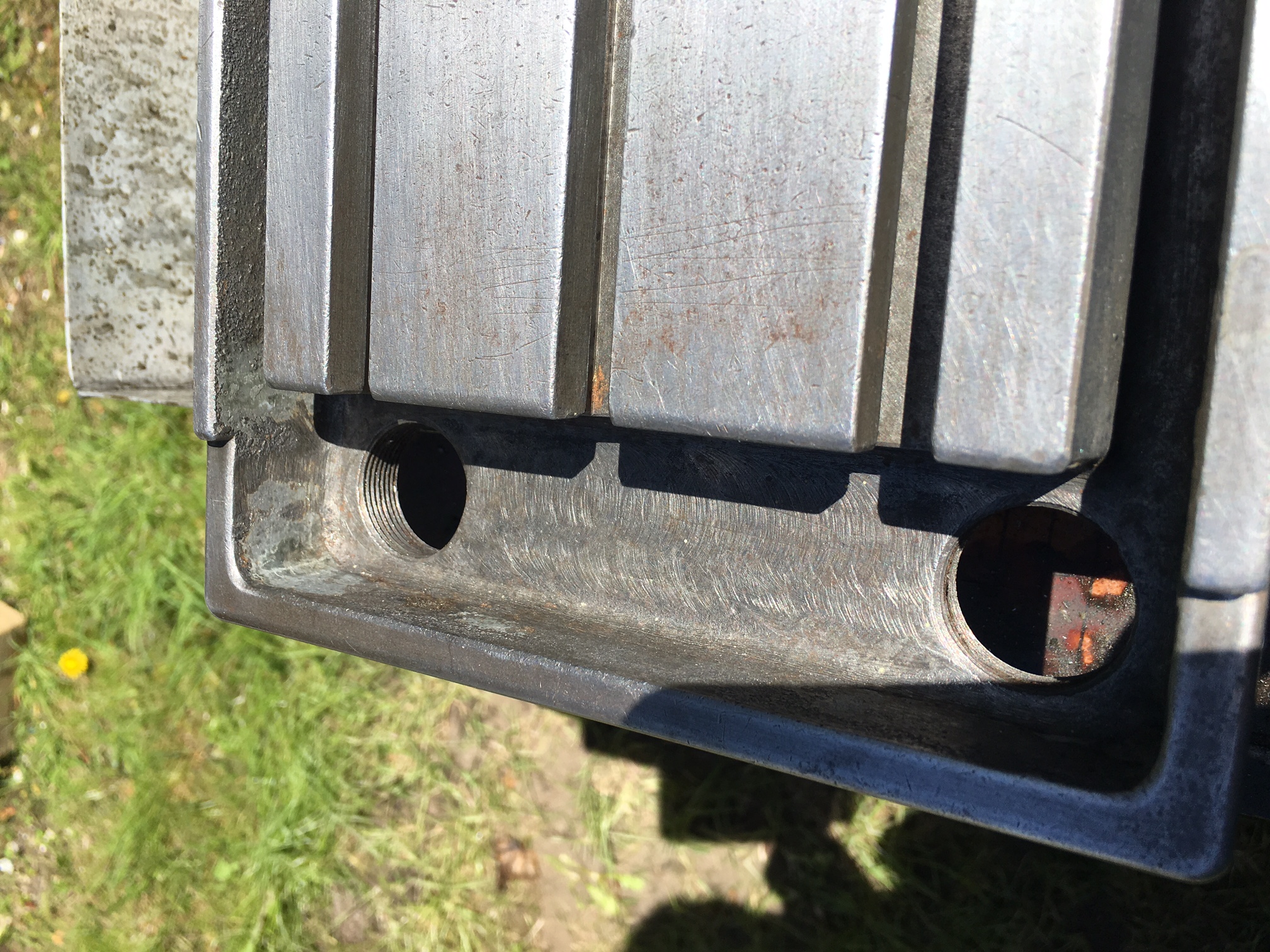
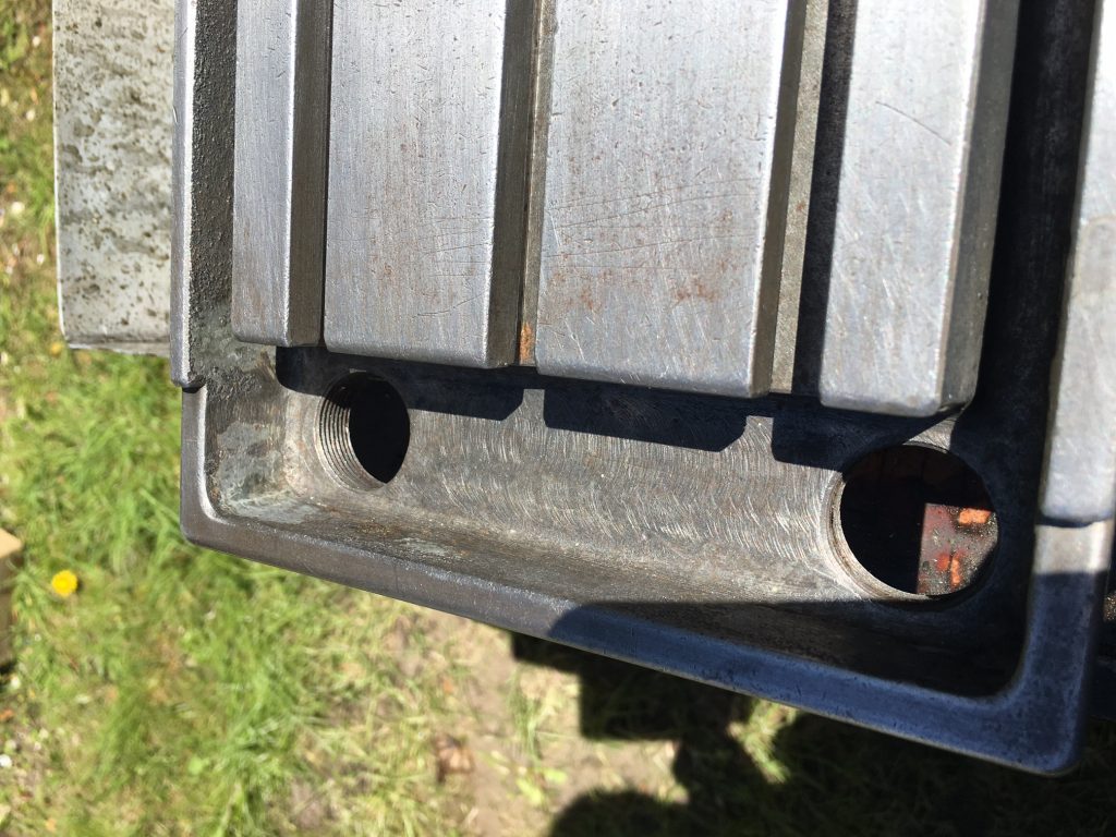
A close up reveals the damage to the top of the table. I’m not sure what to do here. I can either leave well alone or attempt some kind of repair. This needs careful thought. When I bought the mill, I never thought to remove the vise when inspecting the machine – this damage was completly covered by the vise and so I did not see it!
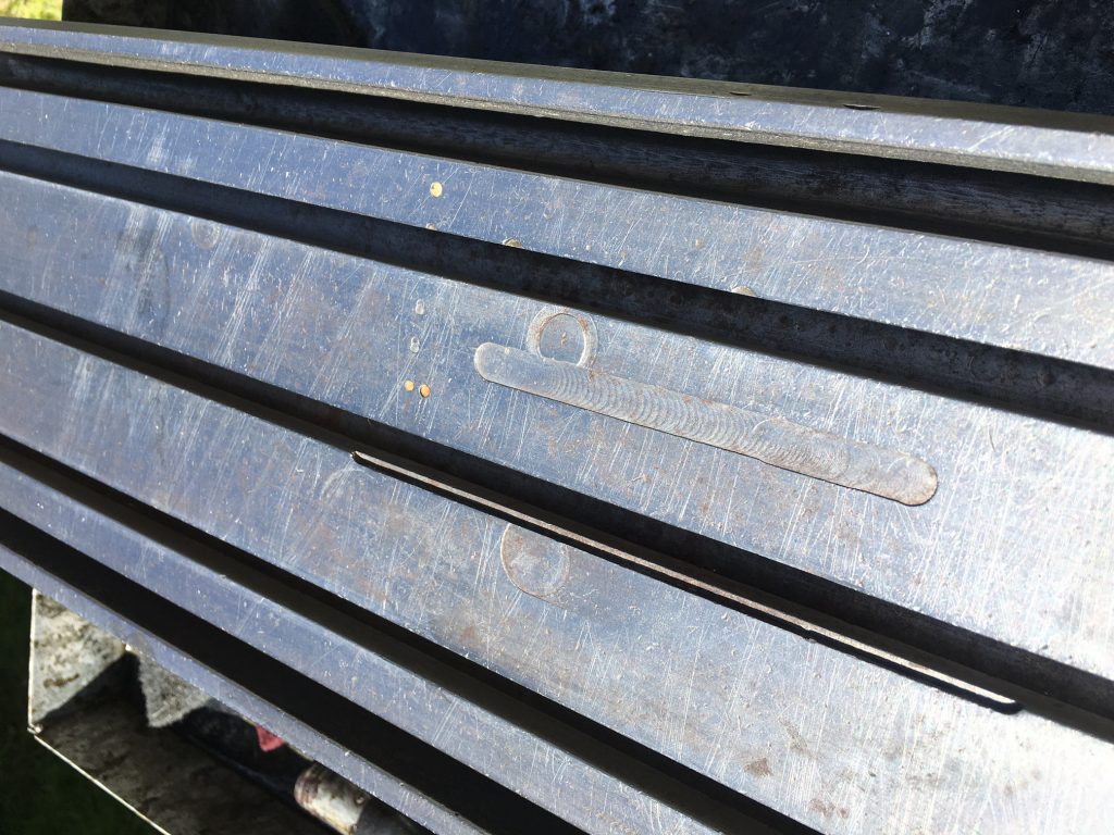
IMG_2747

The oilo traps at the ends of the table were painted as I can see residue of paint. I need to establish if the side channels were painted as well. The screw threads on the drain holes need a good scrape as well!
IMG_2748

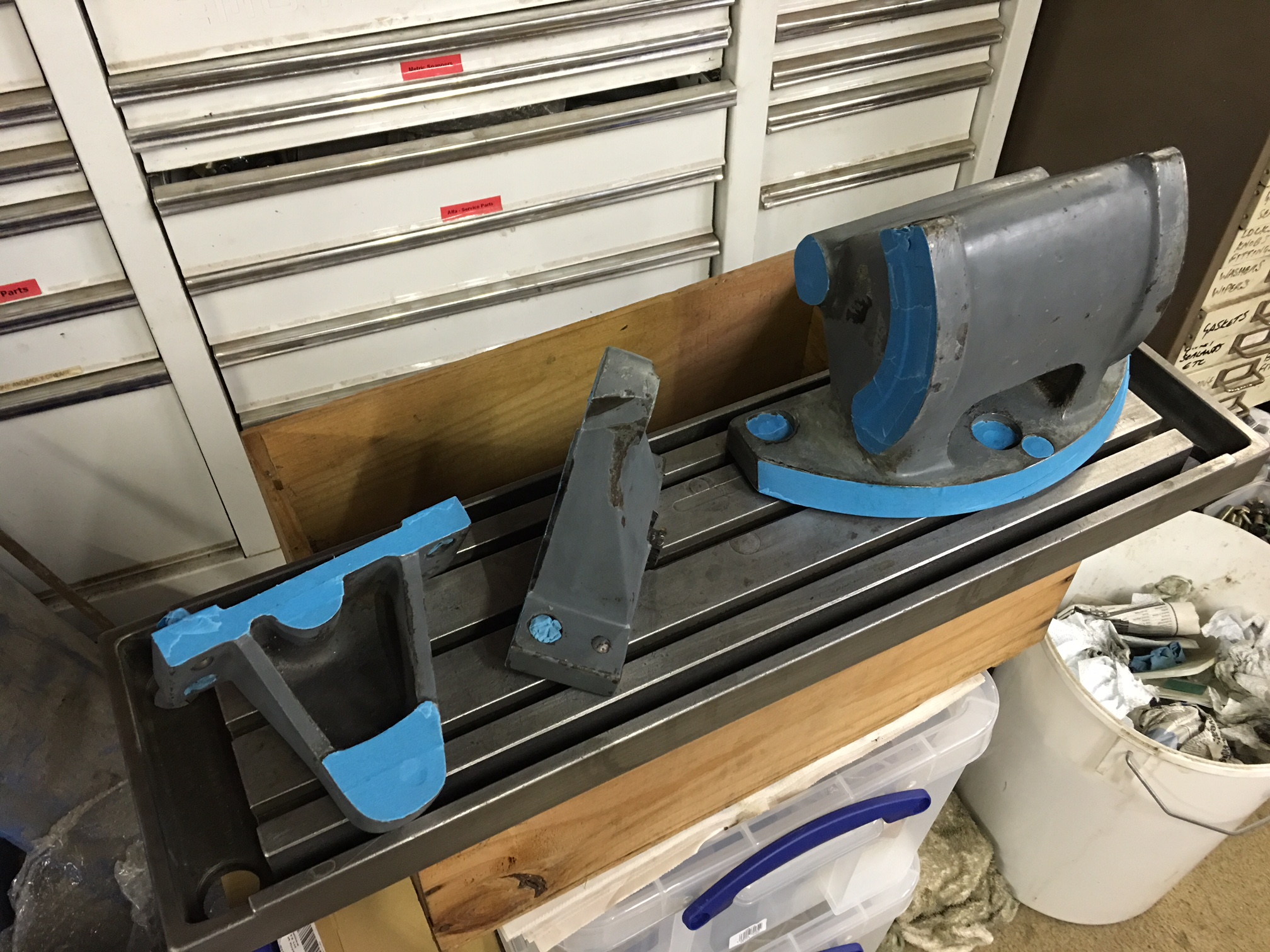
Next stage will be to clean up the tilting mechanism, clean up the meatal a little more and then mask up for spraying.

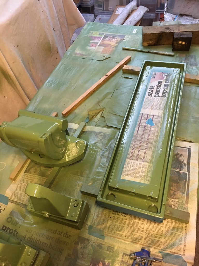
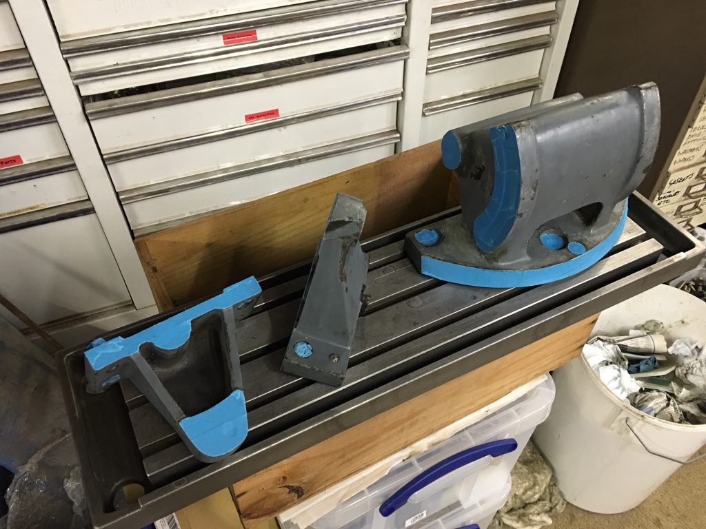
Below are a few items ready for paint
IMG_2765

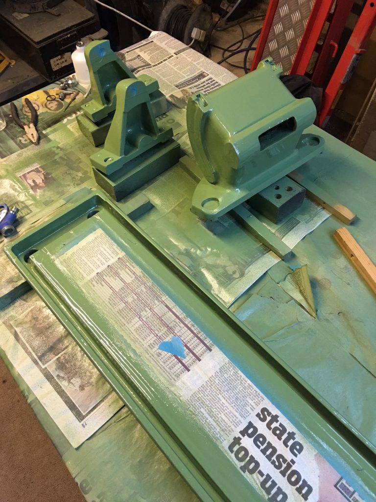
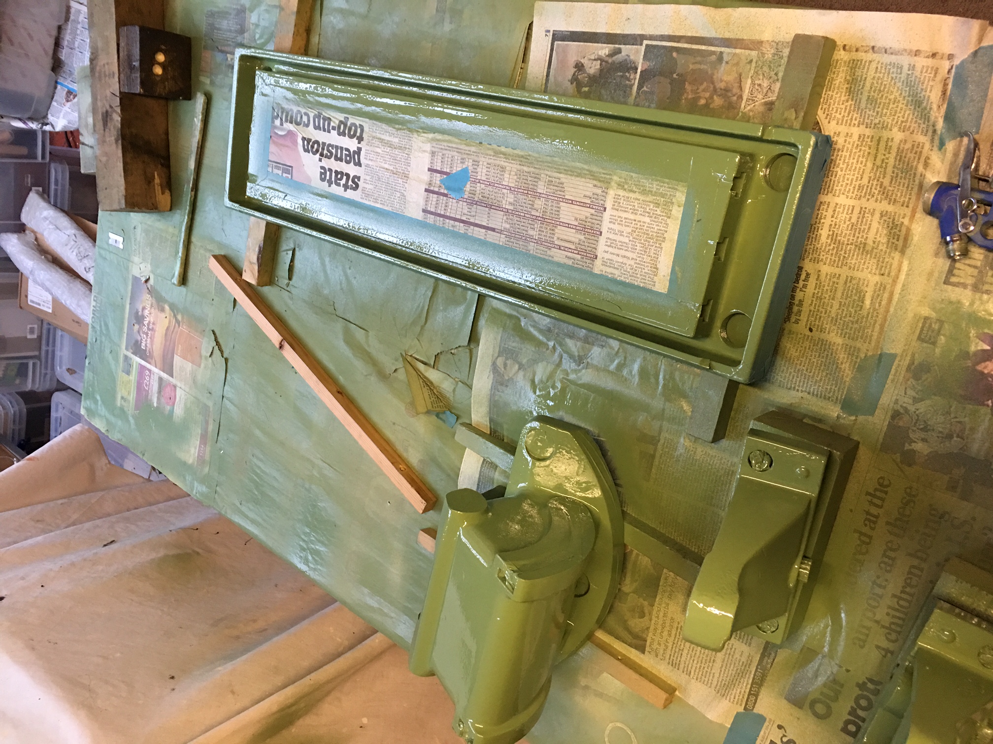
Table masked up and painted

IMG_2766

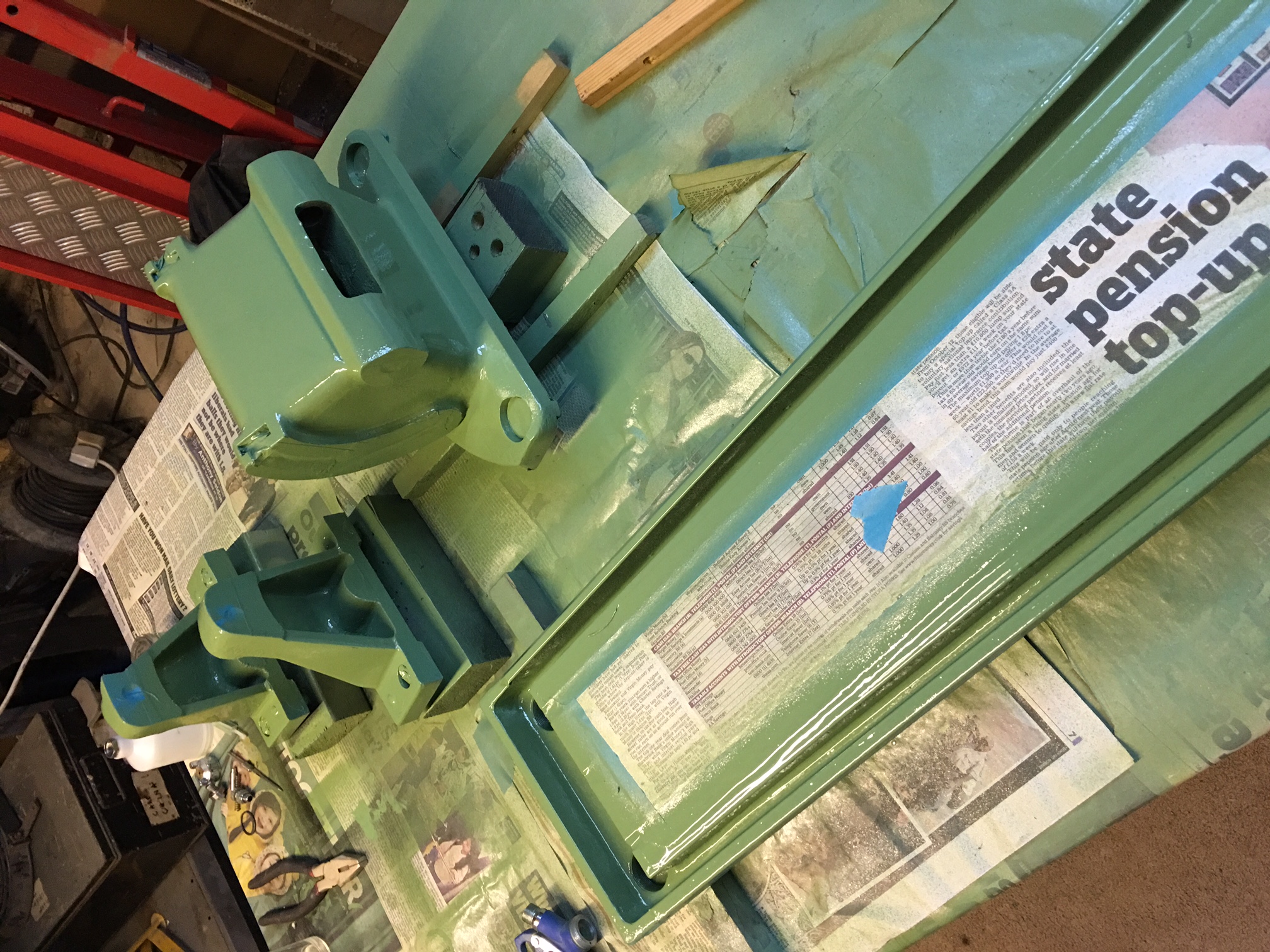
Another view with the brackets etc.

IMG_2767

There isn’t much more painting to do for the F3 – just a little touch up here and there.
Gearbox problem!

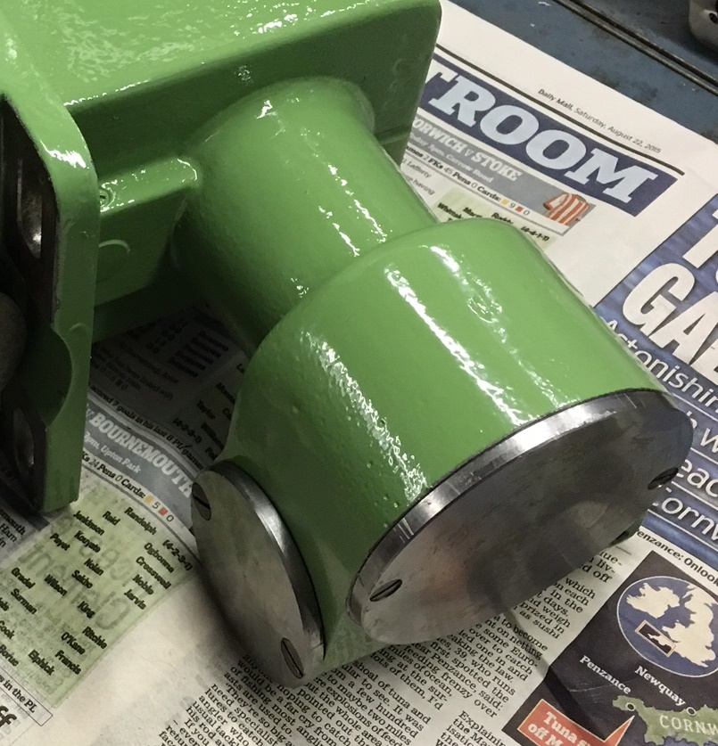
I’m not sure what happens here but after fitting the geabox, I seemed to lose drive to the apron. So I removed the prevoiously fitted pulley and removed the unit. By taking off the round cover plate (the larger one in the foreground) it is possible to push back the rack that the speed selector acts upon. It is in the centre of the gear when you remove the plate. Voila, the gearbox then works again. I think this all came about when I removed the selector dial.

IMG_2667 - Copy

My only issue now is that when I removed the pulley, it shot off the shaft, hit the casing and landed on the motor and you guessed it, it chipped a lump out of the edge. I will braze this all back up and turn up on the lathe. Looking at the chip, it has rust in the broken area and it looks like I dealt the final blow to it breaking off. Photos to follow when I get a moment.

This is the view from the top inside the belt ‘well’ – pulley removed.

IMG_2741

DRO’s

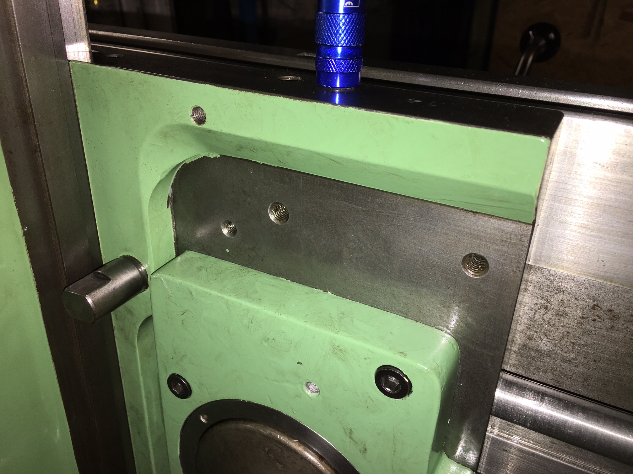
I will be fitting a 3 axis digital readout in due course so I thought I would create a separate section for this. I will add to this as and when I design the decoder mounts etc. What did occur to me was that this machine has two tapped holes in the back of the main carriage ready for mounting the Z decoder: (unless these are used for something else!!)

IMG_2740

Apron slide graduated wheel

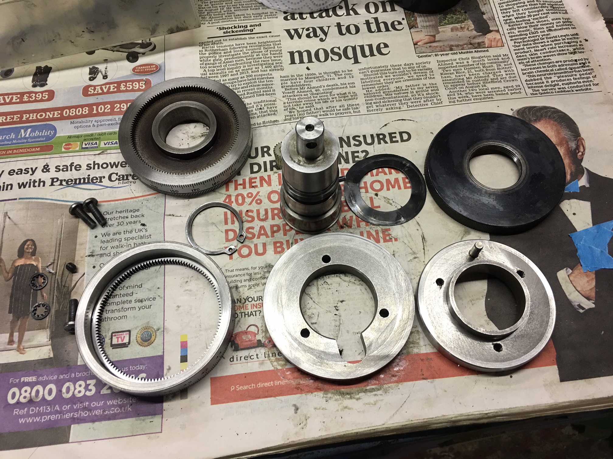
Below, you see one of the twin dials on each of the axes. It seems unecessarily complicated but I suppose there is some good reason the Swiss made it this way! The picture show all the parts except the nylon gear that is hiding behind the screw extension on the left.

IMG_2737

Below, you see the extension fitted to the screw. This is fitted in place with a roll pin – the hole shown ready for the pin to be driven in.

IMG_2738

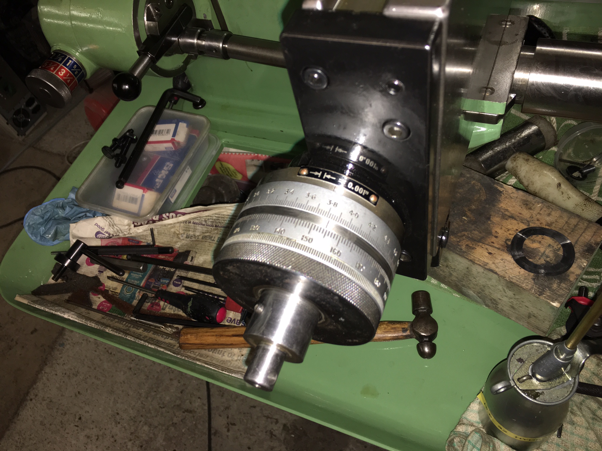
The photo below shows the twin dials fitted.

IMG_2739